Contents
- The Physics Behind The Human Arm
- The Physics Behind The Prosthetic Arm
- Mimicking Life
- Conclusion
- References
The osseointegration of a prosthetic limb has allowed the quality of life for patients with either a mutation at birth that has led to a loss of one or more limbs or have gone through traumatic experiences that has led to this injury. It not only improves the capabilities of one of these patients to manage daily activities but also lets them stay independent.
For many people, an artificial limb can improve mobility and the ability to manage daily activities, as well as provide the means to stay independent.
The Physics Behind The Human Arm
Example: Arm

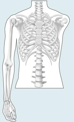
To get an idea of how body parts work and what thinking needs to go into building prosthetics, I will be using very basic Free Body Diagram to demonstrate how an arm works. The model will be of the total removal of the upper arm and forearm.
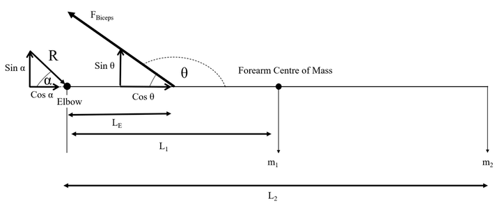
In this example, I will use the free body diagram below to show what forces are being applied to an arm when it is holding something up.
In the following diagram, we know Newton’s 3rd law, where for every force being applied, there is an opposite and equal force (A reaction force), to find the force required to lift the object. We want to find the force required to lift this object.

There are 4 given variables affecting the arm in this example. They are as follows:
- The force produced by the bicep: \(F\)\(Bisceps\)
- The mass of the arm: \(m\)\(1\)
- The mass of the object held: \(m\)\(2\)
- Acceleration due to earth's gravity: \(g = 9.81 \frac{m}{s^2}\)
\(L\)\(E\) is the distance from the elbow to the point of insertion of the bicep muscle.
\(L\)\(1\) is the distance from the elbow to the forearm centre of mass.
\(L\)\(2\) is the distance from the elbow to the held object.
\(\theta\) is the angle at which the bicep muscle is positioned at.
We know that the arm is not moving as there is no change in the arm over time (it's stable), this tells us that the arm is in an equilibrium state and therefore all forces are equal to 0. so we can resolve forces using: \(\sum F = 0\)
As stated before, the arm is not moving and is in equilibrium. From this, we can gather that there is no rotation around an axis as well, so we can take moments (⟳ +) (clockwise direction is positive): \(\sum M = 0\)
In an equilibrium state, forces are equal, so forces in the clockwise direction = forces in the anti-clockwise forces. Therefore if we resolve vertically (↑), we get:
\(m_1 \cdot\) \(g + m_2 \cdot\)\(g + R \cdot \sin(\alpha) = F\)\(Bisceps\) \(\cdot\sin(180 - \theta)\) Now do the same horizontally (→): \(R\cdot\cos(\alpha) = F\)\(Bisceps\) \(\cdot \cos(180 - \theta)\)
Same with moments, there's no rotation as the arm is in equilibrium so we can take moments (⟳ +) about the elbow (we use the elbow as it generates an equation that includes all the relevant variables in it):
\(m_1 \cdot g \cdot L_1 + m_2\cdot g \cdot L_2 = F\)\(Bisceps\) \(\cdot\sin(180 - \theta) \cdot L_E\)
Rearrange to get: \(F\)\(Biceps\) \(= \frac{g(m_1 \cdot L_1 + m_2 \cdot L_2)}{L_E \cdot \sin(180 - \theta)}\)
Now we have \(F\)\(Biceps\)
Next, we put both equations for resolving together to make it easier to follow:
Vertical (↑):
\(m_1 \cdot\) \(g + m_2\cdot\)\(g + R \cdot \sin(\alpha) = F\)\(Bisceps\) \(\cdot\sin(180 - \theta)\)
Horizontal (→):
\(R\cdot\cos(\alpha) = F\)\(Bisceps\) \(\cdot \cos(180 - \theta)\)
As we are using a right angle triangle to calculate and display the forces, seen in figure 2, we can use the Pythagorean equation to find the hypotenuse, which in this case is the reaction force:
\(R = \sqrt{(R\cdot\cos(\alpha)^2 + (R\cdot\sin(\alpha)^2 )}\)And the angle it acted at: \(\tan(\alpha) = \frac{R\cdot\sin(\alpha)}{R\cdot\cos(\alpha)}\) Then: \(\alpha = \arctan(\frac{R\cdot\sin(\alpha)}{R\cdot\cos(\alpha)})\)
This reaction force shows us the minimum requirement the prosthetic needs to withstand to hold the object up with no issues. So building a prosthetics that are strong and sturdy are vital for the patient
The Physics Behind The Prosthetic Arm
Bending Rigidity
Bending rigidity = (Area moment of inertia x Young’s modulus)
Bending rigidity is how much force the object can take before it experiences enough compression and tension and bends, which can eventually lead to failure of the material at certain loads [1]. This is important to understand for prosthetics as they have to withstand enough force to be useful in everyday life while also being light enough to easily be moved around for daily activities that the user may do.
Area moment of inertia
Equation 1: \(I = \frac{\pi(r^4)}{4}\)
Equation 2: \(I = \frac{\pi(r_2^4 - r_1^4)}{4}\)
Where \(I\) = Area moment of inertia (\(mm^4\)) and \(r\) = Radius of the circle (\(mm\))
In classical mechanics, the area moment of inertia is defined as:
“A measure of the ‘efficiency’ of a cross-sectional shape to resist bending caused by loading.” [2]
As bone is hollow it requires an alternative equation (equation 2) to calculate the moment of inertia. The formula used for solid cylindrical objects seen in equation 1 is applied to prosthetics. These differences are kept in mind when researching shapes to use as the prosthetic needs to be able to handle forces applied and resist bending in daily life and activities.
Hollow Bone
In our biological evolution, the development of hollow bone is actually quite an incredible design that uses the limited materials the human body has at its disposal to create a structure that is, at its hardest, the same strength as a steel beam.
Due to the limited resources inside the human body, a hollow bone is actually the most logical solution due to the fact that all the material in the bone is condensed to the edges making the solid part denser and lighter at the same time due to the air pockets created. The empty space is vital for helping transport nutrients and makes the bone a regenerative environment.
Young's Modulus
The youngs modulus is calculated via the following:
\begin{equation*} E = \frac{\frac{F}{A}}{\frac{\Delta L}{L}}\ \end{equation*}
Where:
The Young’s modulus is a mechanical property that measures the stiffness of a solid material [3]. This is calculated by plotting a \(\frac{stress}{strain} (\frac{\sigma}{\epsilon})\) graph and finding the gradient of the graph. The gradient is the young’s modulus. High young’s modulus values show a material that can handle large loads but is not flexible and a low modulus is the inverse. So a compromise must be found between these two values to find the best material for the prosthetic.
Centre of Mass
\begin{equation*} CoM = \frac{g(m_1 \cdot L_1 + m_2 \cdot L_2)}{g(m_1 + m_2)}\ \end{equation*}
For amputees, one issue they have to be adjusted to and for engineers to consider, is the centre of mass. The loss of a limb is a loss of a large mass on one side of a person, thus altering the centre of mass of the patient when compared to the average person. The force of gravity is assumed to act at this point on the person and rotational force also occurs in this place and therefore has to be taken into consideration when deciding the mass of the prosthetic and may also be used in planning the physiotherapy for the patient later.
Mimicking Life
While these artificial limbs have progressed leaps and bounds, from their mobility to their functionality, they are still just that, artificial. Previously, the cold metal prosthetic does not have the same feel to that of a human limb, to touch and feel. Products such as the “Electric Skin” help people who miss the sense of touch by providing the artificial limb the one thing it’s missing, artificial skin. The “Electric Skin” stimulates the nerve endings in the hand and creates a sense of touch by sensing stimuli and relaying the impulses back to the peripheral nerves [4].
Conclusion
These are only a few of the components (not including the electronic engineering aspect), that I've learned of, which I find most interesting when studying prosthetics and I believe that these are quite important when creating a holistic design suitable for a patient's use.
References
[1] Winn, Will (2010). Introduction to Understandable Physics: Volume I - Mechanics
[2] Learn Easy, MDME: MANUFACTURING, DESIGN, MECHANICAL ENGINEERING, Area Moment of Interia, published August 21, 2014 [Accessed 18 June 2020]
[3] The Rational mechanics of Flexible or Elastic Bodies, 1638–1788: Introduction to Leonhardi Euleri Opera Omnia, vol. X and XI, Seriei Secundae. Orell Fussli.
[4] John Hopkins University, Written by Amy Lunday, Biomedical engineering Bringing a human touch to modern prosthetics , published Jun 20, 2018 [Accessed 20 June 2020]